|
Single rotate
mechanism
This is where it gets a bit tricky!
There are a number of mechanisms employed
by Mousetrap that I tend to regard
as 'Standard' but which may be very
new to some Spanners. The first is
one I call a 'Single Rotate Mechanism'
whose output shaft is designed to
rotate just once. This output shaft
may, or may not, allow one or more
'Pulses' to be output which drive
mechanisms similar to itself.
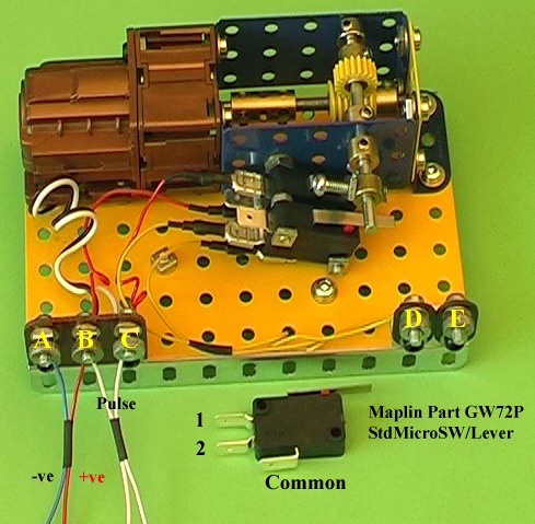
This picture (and the next one) show
a demonstration mechanism that employs
standard micro switches that may be
obtained from Maplins. They are particularly
useful since they have ready made
attachment holes which are almost
exactly one inch apart and are easily
bored out to 4mm. The two pics should
be viewed together if possible. Ignore
the switch furthest away from the
flanged plates together with its yellow
wiring for the moment, and concentrate
on the other switch and terminals
A, B and C. Also ignore the white
wires to Terminals B and C.
The wiring is as follows:
Motor -ve to Terminal A (Black)
Motor +ve to Terminal C (White)
Switch Common to Terminal B (Red)
Switch (1) to Terminal C (Red)
6 volt -ve to Terminal A (Blue)
6 volt +ve to Terminal B (Red)
Now, if the lever of the switch is
in the raised position then the motor
receives current and the output shaft
(with the 19 tooth gear) rotates clockwise.
However, if the lever is depressed
then no current flows and the output
shaft stops.
Now consider the 1/2" bolt in the
collar just above the switch. This
is adjusted so that as the shaft rotates
this bolt will depress the lever and
so cut off the current and so stop
the motor.
It should now also be noted that if
Terminals B and C are shorted together,
then current also flows and the motor
will start.
OK. Now bring in the two white wires.
If these are shorted together for
just a short time (say <= 1 second)
then the output shaft will rotate
long enough for the 1/2" bolt to stop
depressing the lever, normal current
will flow and the output shaft will
make one complete revolution before
the bolt once again depresses the
lever.
Good. So far we have a mechanism that
will allow an output shaft to rotate
exactly once.
Now consider the second switch. This
is wired as follows:
Switch Common to Terminal D (Yellow)
Switch (2) to Terminal E (Yellow)
It is now fairly obvious that the
second 1/2" bolt above the second
switch can be used as a source of
a 'Short' or Pulse, when its lever
is depressed, to provide input for
a following mechanism similar to this
one. In fact the output shaft can
be used to provide any number of pulses.
For example, Mousetrap uses a mechanism
that provides for up to five pulses.
When I first designed this mechanism
(it seems ages ago) I built two and
coupled them together to provide pulses
for each other and watched them for
ages!
This, however, will now be left as
an exercise for the student (as I
used to say in my lecturing days!).
Anyway, build it if you like - it's
very useful.
The next picture shows how they are
used.
|