|
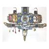
About the Model:
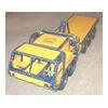
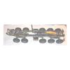
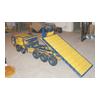
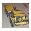
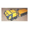
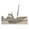
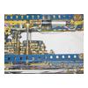
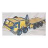
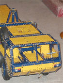
This is a model of an Oshkosh PLS Vehicle.
PLS stands for Palletised Load System. This
refers to the system used to quickly load
and unload pallets of materials at the front
line of battle.
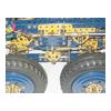
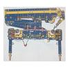
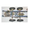
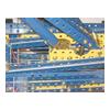
The vehicle has 10 wheel drive, driven
through a 5 speed epicyclic gearbox and
a two speed torque splitting transfer case.
The drive from the transfer case splits
the drive to 5 axles through 3 inter-axle
differentials. All axle differentials are
lockable, as are the inter-axle differentials.
There is an epicyclic hub reduction to each
wheel. The front tandem axle steers, as
does the rear most axle, to reduce the turning
circle of the vehicle.
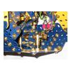
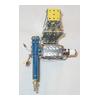
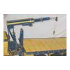
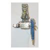
There is a small materials handling crane
situated behind the engine and gearbox.
This has two outrigger feet and revolves
180 degrees on its turntable. Two rams raise
the crane into the air. The crane arm has
an outer section with a further 3 extending
sections inside it. The load is carried
by a hook and rope.
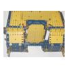
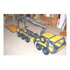
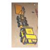
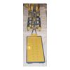
The rear of the chassis has the loading
and unloading system operated in two sections
using hydraulic rams.
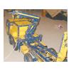
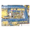
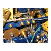
All of these features have been reproduced
on the model. Hydraulics have been simulated
using either cord and wire systems or rotating
screwed rods. The motive power for the transmission
is a Marx Hectoperm motor. The epicyclic
gearbox uses 2.5" gear rings with 19t pinions
as sun and planet wheels.
The material handling crane is operated
via 7 switches located on the side of the
model. There is also a remote switch which
can be plugged into the model which will
operate the crane and the rear demountable
pallet. The cab houses switches for operating
two sets of diff locks and a 2nd set of
controls for the rear platform.
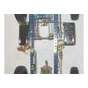
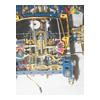
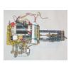
The transmission, including both gearboxes,
steering and rear platform are all radio
controlled. The epicyclic gearbox is electrically
operated via electromagnetic clutches which
are used to brake each annulus to select
the gear. A 5 position rotary switch operated
by a servo connects each clutch in turn
to a power supply.
The power for the model comes from onboard
batteries. There is also a facility to plug
in an external power source.
The model has taken about 3 years to build.
Over 100 nineteen tooth pinions have been
used in the transmission and there are 13
motors in all.
DETAILS
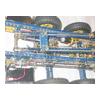
1. Steering. The original vehicle has hydraulic
power assisted steering, with the steering
drive to the rear axle being a shaft drive
down the side of the vehicle, with a gear
reduction/reversal gearbox part way down.
In the model, all the steering boxes are
operated by worm and pinion, as this looked
very much like the real machine. It was
then possible to have the drive to the rear
steering axle as per the prototype. To overcome
the limitations of the worm drives, thrust
races were used for each one. They were
formed from small bevel gears trapping 7
small ball bearings against a washer (these
were also used in the helical drives to
the axles).
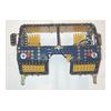
2. Cab. The cab is removable like the real
vehicle. Power connections plug in for the
switches which control the diff lock servo
motors and the demountable load system.
The steering drive is taken to the vehicle
via a dog clutch. The seats can recline
and they are also sprung.
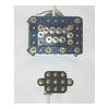
3. Diff locks. The axle differential cases
have a bossless 57 tooth gear bolted to
one side (this part was included in the
Action Packs with the sprint motor in 1981).
Immediately beside this, a 57t gear is locked
to the half shaft. A 19 tooth pinion on
a sliding shaft below can be brought into
mesh with both gears to lock the diff. This
is operated by a Bowden cable actuated by
a lever which is moved using a single eccentric.
The eccentric is driven by a small motor
with suitable gear reduction.
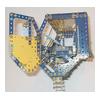
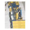
4. Crane and transmission. This whole unit
can be removed from the chassis be undoing
two bolts. The crane can then be removed
from the gearbox structure by removing a
further four bolts, together with the slewing
pinion. When the whole unit is replaced
on the chassis, a pair of drifts at the
cab end aid location into to journals formed
by the chassis members with cranks bolted
below. The vertical drive to the slewing
action of the crane is picked up by a worm
gear on a shaft running at right angles
to the chassis.
5. Power Supply. The model is driven by
onboard batteries. One battery powers the
transmission and all of the radio control
gear. Two more 12 volt units power the crane,
unloading system and the diff lock servos.
There is the facility to plug in an external
supply to take over from the 12 volt units.
A pair of 9 volt cells are used for the
power supply to the gearbox selector unit.
The non standard parts used in the model
are as follows
1 2.5" gear rings
2 5.75" rubber tyres
3 30/45 and 22/55 gear pairs from Exacto
4 Mini Single pole, double throw, centre
off switches
5 Motors
6 Nylon coated fishing wire
7 Narrow face 19t pinions
8 MW long sleeve pieces
9 Small ball bearings used in thrust races.
|