|
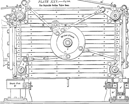
Reynolds diagram
No 1.
Drawings are 1:1 scale assuming 5.5
x 3.5" flat plates are use for the
sides and 4.5 x 2.5" for the ends.
- This drawing shows the basic layout
of the wrist plate, bell cranks, valve
and governor linkages. The 2 inlet
valves are at the top and the exhausts
are at the bottom.
(Click image above for full-size
version)
|