|
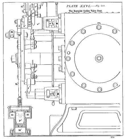
Reynolds diagram No
2.
End elevation showing construction of the
cylinder, the valve bonnets and relative
positions of the valve operating levers,
inlet valve bell cranks, the governor levers
and dashpots with their levers and rods.
1" square valve blocks and machined bonnets
are used on the model.
(Click image above for full-size version)
|